RealityScan - Coded Markers
RealityScan for professionals
For us as an engineering office with decades of experience in high-quality 3D surveying with different surveying technologies, the software RealityScan from Epic Games is unique! No other comparable product has ever been so fast, so precise and so powerful in our use. That’s why we rely exclusively on RealityScan (formerly know as RealityCapture) when it comes to the processing of photogrammetry data and in combination with laser scan data, for generating 3D point clouds and creating 3D models. We love it!
Create 3D models from photos is now even easier using the right photogrammetry accessories.
Coded Markers or Targets for everyday surveying
For an improved workflow, we offer RealityScan Markers in the form of stable, reusable CodedTargets. Why we use these ourselves is obvious:
- Faster, more accurate and optimized alignment
- Simplifies the registration process for complex structures
- Manual addition of tiepoints no longer necessary
- Can also be used as (ground) control points
- Improve the fusion of active and passive sensors - laser scans, photos and video frames
- Existing measurement unit aids with scaling scenes
- Automatically mark position for higher accuracy
- Produced and suitable exclusively for the RealityScan photogrammetry software

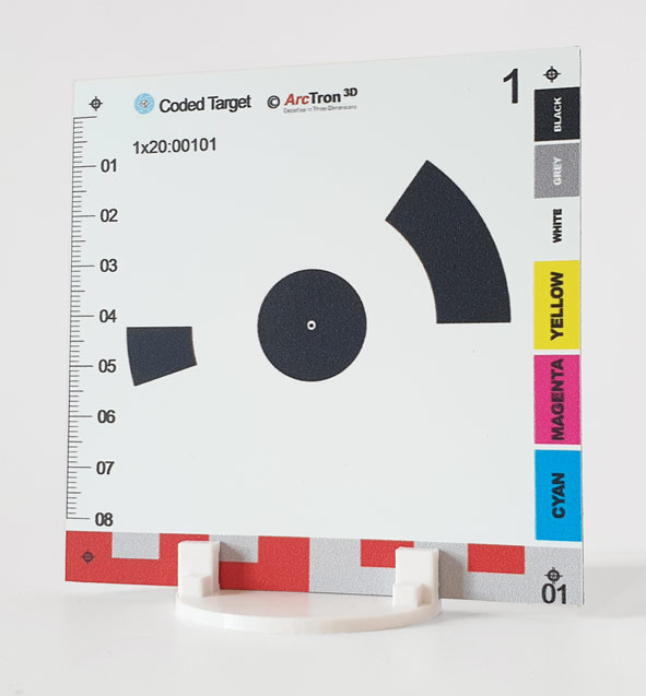
– 10x10cm CTs (numbers 1-100) for measuring small and medium-sized objects or rooms
– 15x15cm CTs (numbers 301-350) for the measurement of facades or halls
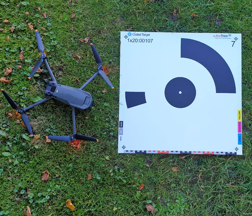
– 55x55cm CTs (numbers 01-20) for drone photogrammetry, aerial surveying at low and medium altitudes
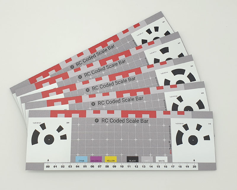
– Coded ScaleBars 20cm (bar size 26x8cm) (numbers 201-210) for correct scaling. ScaleBars can be combined with other CTs
– Coded ScaleBars 100cm (bar size 112x14cm) (numbers 201-210) for correct scaling. ScaleBars can be combined with other CTs
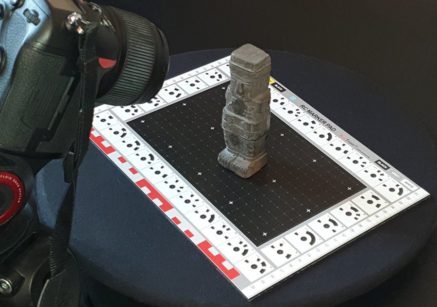
– Coded Markerpad Turntable, diameter 40 cm (numbers 101-130) for 360° detection of small and medium-sized objects
The RC-Tool „Detect Markers” creates connection points for each CT detected. However, it is possible to change the type of control points after detection as Ground Control/Ground Test.
Different CT sizes can be combined within a project, but it should be noted that each CT number may only be used once per project. This also applies if, for example, different floors of a building are being measured. To avoid errors, use CTs with different numbers for each floor or area (e.g. use CTs 1-30 for area 1 and CTs 31-60 for area 2 etc.). If RealityScan recognizes two or more of the same CT numbers within a project during alignment, the control points are displayed on at least two images with the measurement deviations per image in pixels. If a particular CT is used more than once and appears on photos at different locations within a project, these particular control points must be deactivated. (You can choose how the system should handle the point: “Activate” or “Deactivate”).
It must also be ensured that the CTs are not moved during the imaging process. Photograph the object, the interior, the façade or other areas from all sides and angles without moving the CTs until the measurement process is complete.
Coded Targets for drone flights
- A different motif on each target
- Suitable for outdoor use
- In the size 55 x 55cm
- Ideal for drone flights
Depending on the camera resolution of the drone, the targets will be detected automatically by the Software RealityScan up to approx. 20m to 30m altitude.
Quick guide for the use of drone targets
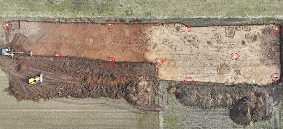
Distribute the CTs around and within your survey area (Fig. above). Before the flight, all CTs should be measured at their center using a total station or GPS and named accordingly.
The CTs should NOT be moved during/after this process until the flight has been completed. At the beginning, we recommend taking at least 3 images directly above each marker at different heights (5-10m height) so that the coded targets are clearly visible and recognizable on the images. Then continue with your flight at the desired height. The measuring points serve as “ground control points” (control points) during the calculation – this is how you obtain the X, Y, Z coordinates.
1. In the optional part of the ALIGNMENT tab, click on the “Detect Markers” button.
2. In the “Detect Markers” toolbar, select the marker type to be detected: “Circular, single ring, 20-bit”.
3. You can select the default number 1 in the “Required measurements” field. (This option filters out marks that are found in fewer than the specified number of images. You can change this entry if necessary).
TIPP: Set “Required Measurements” to a value greater than 1 to reliably detect markers and prevent a marker from being detected on only one image. This assumes that extensive image material is available.
4. Select the image layer on which the markers are to be recognized (if several layers are used).
5. Click on the “Detect markers” button to start the detection of the markers/coded targes in the images.
TIPP: These steps can be used for all CodedTargets products (drone targets, small coded targets, turntables or coded scalebars).
6. After detection, change the type of control point to “Ground Control Points” (ground control or ground test) if you have measured the drone targets using GPS or total station and define the specific coordinate system and the coordinates of the ground control points.
7. Import your Ground Control Points
You can also find detailed instructions on the CapturingReality.com website:
https://rchelp.capturingreality.com/en-US/tools/gcpimport.htm
How to use ScaleBars
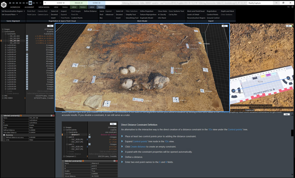
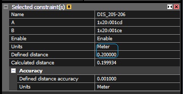
For correct scaling of photogrammetry models, we recommend the use of ScaleBars when recording data. The control points placed in the ScaleBar are at a fixed distance of 20 cm from each other.
By adding distance constraints, this distance of the control points is defined in the 1Ds view and thus a scaling reference is created in the 3D model.
Prices for photogrammetric accessories
Photogrammetry turntable with 40cm Ø
manual, only works with RealityScan/RealityCapture from Epic Games-
For faster and more precise alignment and for easy scaling
-
Works only with RealityScan (not with other photogrammetrie software products)
-
Material: AluDibond semi matt surface
-
Incl. orientation cone
-
Diameter: 40cm
-
Ideal for capturing very small objects up to a size of approx. 30cm.
Preise in netto zzgl. MwSt. und Versand.
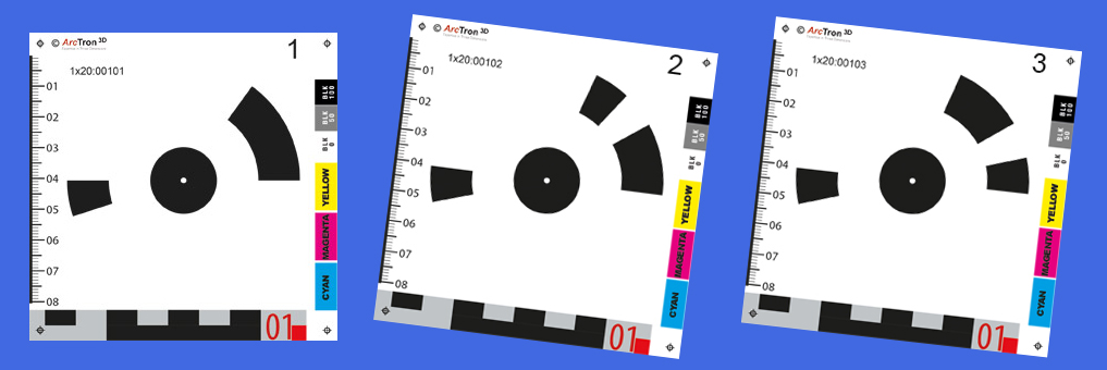
Coded Targets 10 x 10cm
In- and Outdoor Targets for Photogrammetry with RC-
each target a different motive
-
AluDibond direct print on one side
-
with UV-Lack matt coading
-
size: 10cm x10cm
-
Ideal for recording objects, interiors, etc.
Coded Targets 15 x 15cm
In and Outdoor Targets for Photogrammetry with RC-
each target a different motive
-
AluDibond direct print on one side
-
with UV-Lack matt coading
-
size: 15cm x15cm
-
Ideal for recording larger objects, hall, facade and outdoor surveys etc.
All prices net plus VAT and plus packaging/shipping
The CodedTargets offered here ONLY work with the RealityScan software and are not compatible with other software products.
Base plate round for CodedTargets
Flexible application for photogrammetric measurement-
Base plate for up to 4 CodedTargets
-
Made of sturdy plastic - CodedTargets available separately
-
incl. interchangeable plate for photo tripod
-
also available as a set
-
Made of sturdy plastic for fixing up to 4 Coded Targets (for CT size 10x10cm or 15x15cm - not included in the price) e.g. on a tripod or free-standing
-
CT base plate inc. lite tripot - mini set 114,90 €
1 pc. CT base plate, 1 pc. lite tripot, 10 pcs. CodedTargets 10x10cm
-
CT base plate incl. lite tripot - medi set 219,90 €
2 pc. CT base plate, 2 pcs. lite tripot, 20 pcs. CodedTargets 10x10cm
-
CT base plate incl. lite tripot - maxi set 268,90 €
2 pc. CT base plate, 2 pcs. lite tripot, 20 pcs. CodedTargets 15x15cm
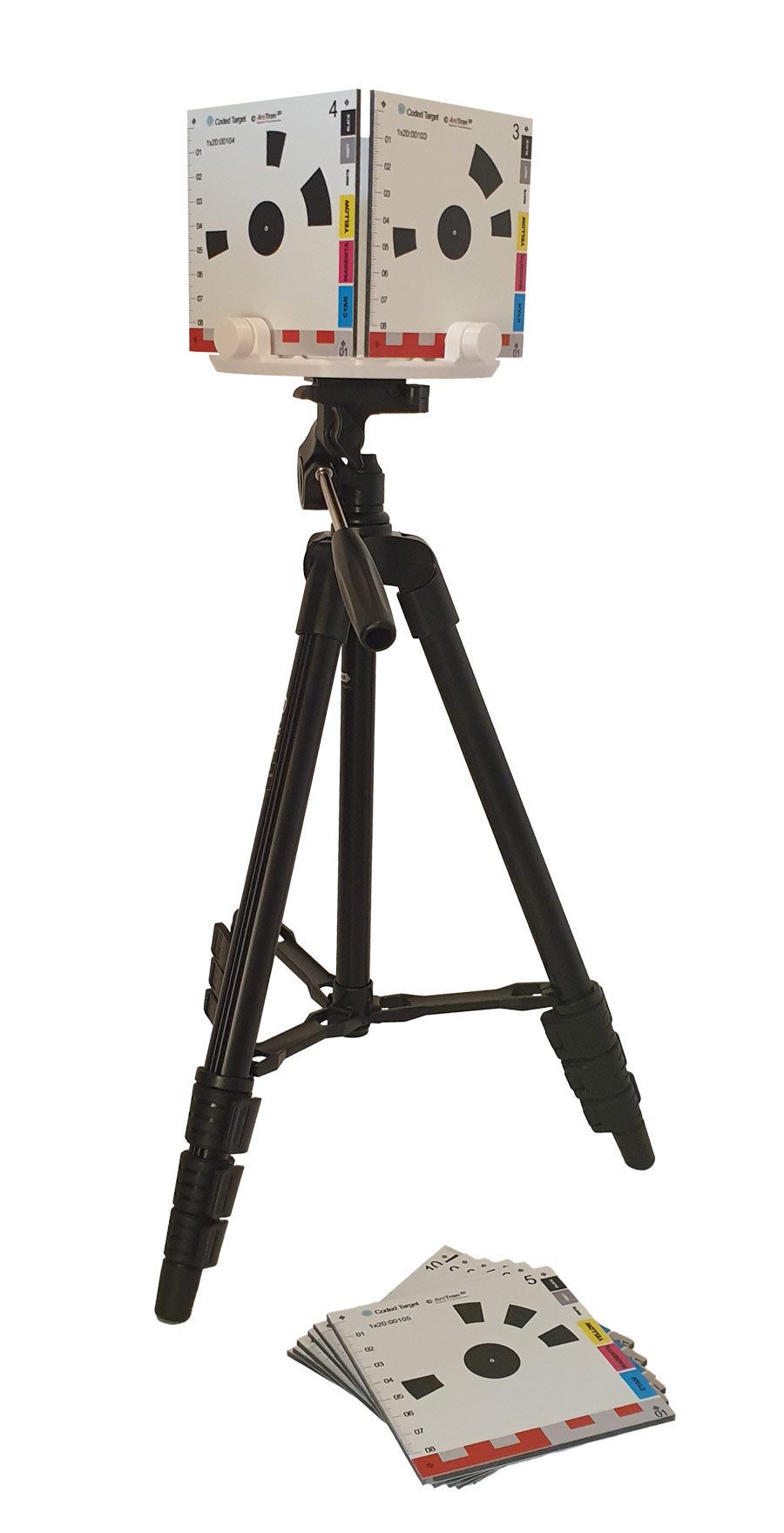
All prices net plus VAT and plus packaging/shipping
The CodedTargets offered here ONLY work with the RealityScan software and are not compatible with other software products.
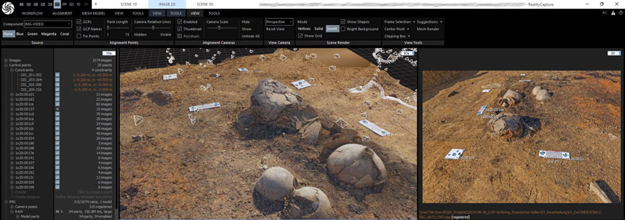
Coded ScaleBar
In- and Outdoor Marker ruler for photogrammetry with RC-
Each scale bar has two different coded targets/target markers
-
On AluDibond in direct print (one-sided)
-
with UV protection
-
size 26cm x 8cm (20cm distance of the marker centers)
-
For scaling during measurement and data processing with RC
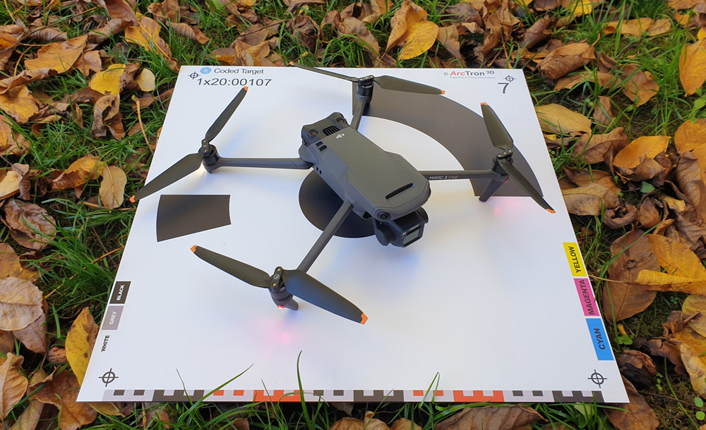
Coded Targets for drone flights
Targets for Photogrammetry with RC-
each target a different motive
-
AluDibond direct print on one side
-
with UV-Lack matt coading
-
size: 55cm x55cm
-
ideal for drone flights
-
drone not included
RealityScan Training
Book one-day training courses with us in face-to-face and online seminars. We build on your individual level of knowledge – whether for beginners or advanced users. Give us a call or send us an inquiry by email.
